Bosch 4410 Owner's Manual
Browse online or download Owner's Manual for Circular saws Bosch 4410. Bosch 4410 Owner`s manual User Manual
- Page / 15
- Table of contents
- BOOKMARKS
Summary of Contents
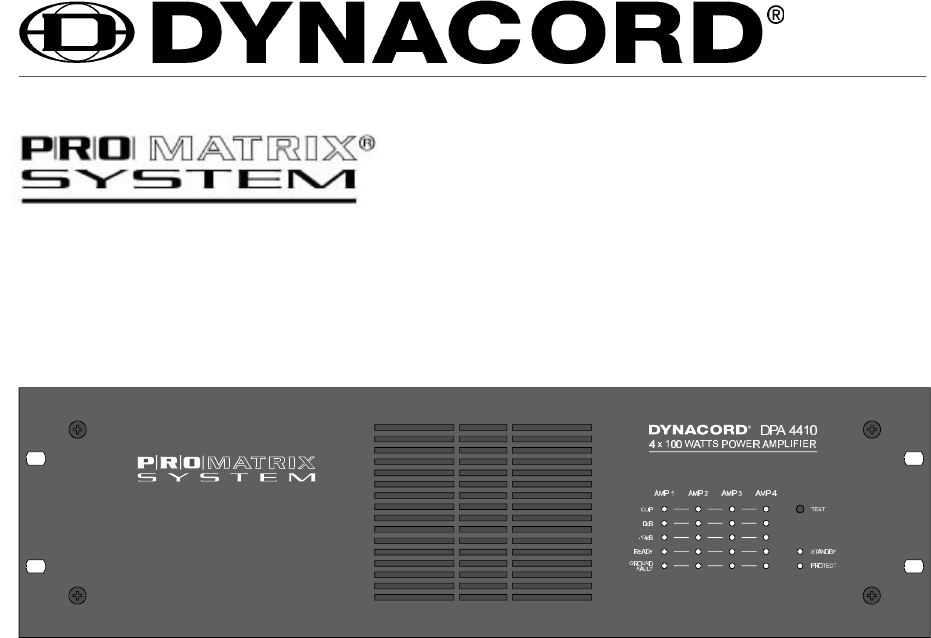
DPA 4410 POWER AMPLIFIER Features• 4 x 100 W output capacity• off ground potential 100 V outputs (internally configurable to 70 V/50 V or 4 ohm
Diagram 7 Changing the output transformer’s 354030 output voltage9. ADDITIONAL FUNCTIONS AND FEATURES9.1 NRS 90206 pilot tone surveillanceUsing the
Checking the functioning:With built-in NRS 90206 and operational amplifier, the READY indicators (7) have to be lit. Use the TESTbutton (3) to check a
Diagram 9 Printed circuit board 81330.1 with inserted input transformers NRS9020810. INCORPORATION INTO 19" FLIGHTCASES OR 19" RACK
Diagram 10 printed circuit board 85264.2 with inserted DC fuses F502 and F507Changing the fuses F502 and F503:The battery fuses F 502 and F503
12. SPECIFICATIONS OF THE DPA 4410Mains supply:Voltage: 115 V / 230 V~ AC, ±10Frequency: 50 - 60 Protection class: Imains supply U
Monitor output characteristics: unbalancedNominal output voltage 2 V = +8.2 dBuNominal load impedance 600 ohmsOverall frequency response 6
The lightning flash with arrowhead symbol, within anequilateral triangle is intended to alert the user to thepresence of uninsulated “dangerous voltag
INDICATORS, CONTROLS AND CONNECTIONS 1 LED meters 2 CLIP indicator 3 TEST button for checking and reset 4 STANDBY indicator 5 PROTECT indicator
TABLE OF CONTENTS FEATURES . . . . . . . . . . . . . . . . . . . . . . . . . . . . . . . . . . . . . . . . . . . . . . . . . . . . . . . . 1
1. GENERAL NOTESThe amplifier DPA 4410 has been specially designed to ensure durable performance and reliableoperation of sound reinforcement systems
4. INPUTS 1 - 4The inputs 1 - 4 (14) are electronically balanced. With a sensitivity of 775 mV = 0 dB, they are meant forthe connection of common cont
5.2 POWER OUTPUT with 100 V speaker systemsThe use of speaker systems with a 100 V matching transformer is recommended to reduce the lack inperforman
5.4 POWER OUTPUT 100 V with double output capacityIf the output power of one output is not sufficient to feed all cabinets that are incorporated with
Diagram 6 Pin-assignment of the REMOTE CONTROL D-Sub connector 6. METERINGThe green LED indicator (1) permits the continuous monitoring of the outpu
Related products and manuals for Circular saws Bosch 4410
 (8 pages)
 (48 pages)
 (187 pages)
(76 pages)
(187 pages)
(76 pages)
© 2020, manymanuals.com. All rights reserved. | 0.566 s |
 Manymanuals.com
 Manymanuals.de
 Manymanuals.fr
 Manymanuals.it
 Manymanuals.pl
 Manymanuals.cz
 Manymanuals.es
 Manymanuals-pt.com
Comments to this Manuals