Bosch 430 Operations Instructions Page 22
- Page / 92
- Table of contents
- BOOKMARKS
- Video Recorder 430/451 Series 1
- Table of Contents 3
- 1.1 Safety precautions 7
- 1.3 Important Notices 9
- 1.4 FCC and UL 11
- 1.5 Bosch notices 12
- 2 Introduction 13
- 2.2 Unpacking 14
- 2.3 Installation environment 15
- 2.4 Associated equipment 15
- 2.5 Warranty 15
- 3 Quick install 16
- 3.2 First-time use 17
- 3.3 Quick install menu 18
- 3.3.2 Continuous Recording 19
- 3.3.3 Network 20
- 4 Hardware setup 21
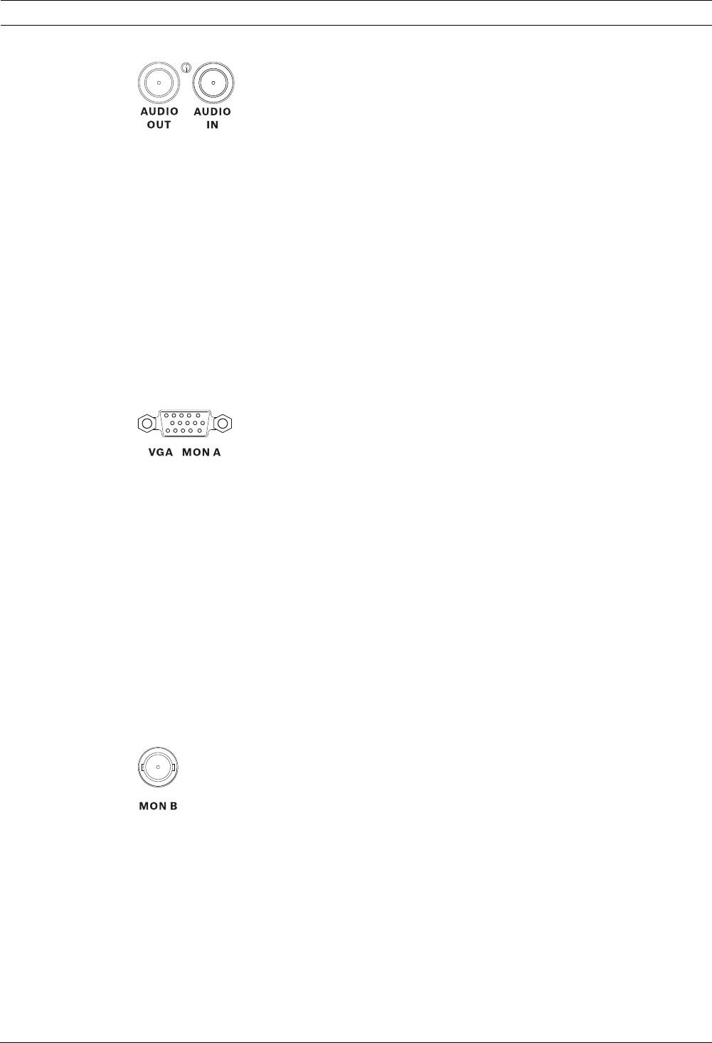
- 4.3 Monitor connections 22
- 4.5 Ethernet connection 24
- 4.6 RS485 port 24
- 4.7 USB connectors 25
- 4.9 Power supply 26
- 4.10 Maintenance 26
- 5 Operating instructions 27
- 5.1.1 Keys 28
- 5.1.2 Indicators 29
- 5.2 Mouse Controls 30
- 5.3 Remote control 31
- QuadSingle 32
- 5.5 Live and playback 34
- 5.6.2 Access using the mouse 35
- 5.6.3 Main menu 36
- 5.7 Search 37
- 5.7.1 Date/time search 38
- 5.7.2 Event search 39
- 5.7.3 Smart search 40
- 5.8 Export 41
- 5.9 System information 42
- 5.10 Log 43
- 5.11 Triggers and alarms 44
- 5.11.2 Motion events 45
- 5.11.3 Video loss alarm 45
- 5.11.4 Multiple alarms 45
- 6 Configuration menu 46
- 6.1 Camera 48
- 6.1.2 Video adjustment 49
- 6.1.3 PTZ 50
- 6.1.4 Continuous Recording 51
- 6.1.5 Input Recording 52
- 6.1.6 Motion Recording 53
- 6.1.7 Network Live Streaming 53
- 6.1.8 Video format 54
- 6.2 Schedule 55
- 6.3 Display 56
- 6.4 Event 57
- 6.4.2 Motion 58
- 6.4.3 Alarm acknowledge 59
- 6.4.4 System menu 60
- 6.5 Network 61
- 6.5.4 DDNS 63
- 6.5.5 Notification 63
- 6.5.6 Mail 64
- 6.6 System 65
- 6.6.4 Users 66
- 6.6.5 Configuration 67
- 6.6.6 Hard Disk 68
- 6.6.7 System 69
- 7 Web Client Software 70
- 7.2 How to log on 71
- 7.3.1 Live mode 72
- 7.3.2 PTZ camera control 72
- 7.3.3 Camera views 74
- 7.3.4 Playback mode 74
- 7.3.5 Export mode 75
- 7.3.6 Configuration mode 76
- 8 Archive Player 77
- 8.3 Camera Views 78
- 8.4 Viewing Images 79
- 8.6 Find image 80
- 8.7 Video slider bar 80
- 8.8 Checking authenticity 80
- 8.9 Exit button 80
- 9 Menu default values 81
- 10 Technical specifications 85
- 10.1.1 Mechanical 86
- 10.1.2 Environmental 86
- 10.2 DVD compatibility 87
- 10.3 USB memory sticks 87
- A Appendix 88
- Bosch Security Systems 92
Related products and manuals for Digital Video Recorders (DVR) Bosch 430
 (158 pages)
 (21 pages)
 (26 pages)
 (12 pages)
© 2020, manymanuals.com. All rights reserved. | 2.753 s |
 Manymanuals.com
 Manymanuals.de
 Manymanuals.fr
 Manymanuals.it
 Manymanuals.pl
 Manymanuals.cz
 Manymanuals.es
 Manymanuals-pt.com
Comments to this Manuals