Bosch DiBos Micro Installation Guide Page 22
- Page / 158
- Table of contents
- TROUBLESHOOTING
- BOOKMARKS
- DiBos/DiBos Micro 1
- Table of Contents 3
- 1Safety Notes 7
- 2 Introduction 11
- 2.5.1 Virus Scanners 12
- 2.5.2 Firewall 12
- 2.6.1 DiBos 14
- 2.6.2 DiBos micro 18
- 3 Device Connections 21
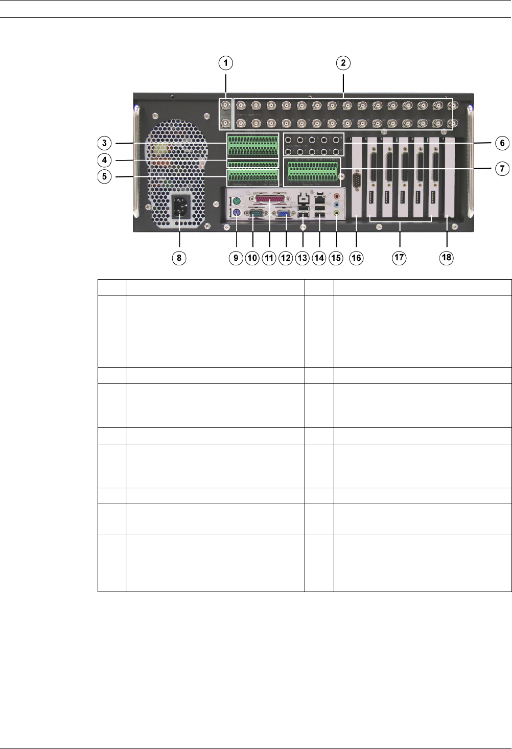
- 3.1.2 DiBos Rear View 22
- 3.1.3 Grabber Card for DiBos 23
- 3.1.4 I/O Card for DiBos 24
- 3.2 DiBos micro 25
- 3.2.2 DiBos micro Rear View 26
- 4 Quick Installation 30
- 5 Quick Configuration 31
- 5.2 Creating a User 33
- 5.3 Setting up the Network 34
- 5.4 Specifying Cameras 36
- 5.5 Assigning Time Profiles 37
- 5.6 Setting Up Recording 38
- 6 Default Configuration 40
- 6.2.1 General Camera Settings 44
- 6.2.7 Editing Audio Settings 54
- 6.4 Configuring Time Periods 71
- 5 Save The entries are saved 72
- 6.5.7 Configuring AP Inputs 82
- 6.5.8 Configuring POS Inputs 86
- 6.11 Configuring Users 107
- NOTICE! 108
- 6.13 Configuring Options 111
- 6.13.1 MIB List for SNMP 114
- 6.13.2 Notification via SNMP 115
- 6.15.1 Activating a License 122
- 7 Remote configuration 123
- 8 XP Administration 124
- 9 Connections 125
- 9.11 Connecting an AP 143
- 9.11.5 Connecting to NZ 1012 147
- 9.11.6 Connecting to NZ 1060 148
- 9.11.9 Connecting to UGM 2020 150
- 10 Troubleshooting and Checks 151
- 11.2 Software Update 156
- 11.3 Troubleshooting 156
Related products and manuals for Digital Video Recorders (DVR) Bosch DiBos Micro
 (52 pages)
 (21 pages)
 (26 pages)
 (12 pages)
© 2020, manymanuals.com. All rights reserved. | 1.224 s |
 Manymanuals.com
 Manymanuals.de
 Manymanuals.fr
 Manymanuals.it
 Manymanuals.pl
 Manymanuals.cz
 Manymanuals.es
 Manymanuals-pt.com
Comments to this Manuals