Bosch B450 Specifications
Browse online or download Specifications for Security access control systems Bosch B450. Bosch B450 Specifications User Manual
- Page / 48
- Table of contents
- BOOKMARKS
- Table of contents 3
- 4 en 4
- Introduction 5
- 6 en 6
- System overview 7
- Bus address settings 8
- Bus address label 9
- Installation 10
- Conettix Plug-in Communicator 11
- Interface 11
- Installation 11
- 12 en 12
- Wire to the control panel 13
- Wire to an SDI2 control panel 14
- Wire to an SDI control panel 15
- 16 en 16
- Configuration 17
- 18 en 18
- Configuration 19
- 20 en 20
- Configuration 21
- Use USB to configure the B450 22
- Configuration 23
- 24 en 24
- Log into the USB interface 25
- 26 en 26
- USB Main menu 27
- USB menu structure 27
- USB menu 28
- Configuration 29
- 30 en 30
- Configuration 31
- Use SMS to configure the B450 32
- Configuration 33
- %1;1=B450;2=secret123;15=3; 34
- %2;19=1;! 34
- Firmware Update page 35
- Figure 5.13: File navigation 37
- Configuration 37
- 38 en 38
- LED status indicators 39
- F01U273558) 43
- Technical specification 44
- Certifications 45
Summary of Contents
Conettix Plug-in Communicator InterfaceB450 en Installation and Operation Guide
InstallationPerform the following steps to install the B450.Notice!Remove all power (AC and Battery) before making any connections. Failure to do so m
12Figure 4.2: Inserting the communication module into the B450Callout ᅳ Description1 ᅳ B44x Plug-in Communicator module (available separately)2 ᅳ B450
Figure 4.3: Mounting the module to the exterior wall of the enclosureCallout ᅳ Description1 ᅳ B4502 ᅳ Enclosure (outside wall shown)3 ᅳ Mounting screw
1. Place the magnetic antenna on top of the enclosure, or vertically on another metalsurface.Notice!If you are experiencing a weak signal, place the a
Notice!Use either the terminal strip wiring or interconnect cable to wire to the control panel. Do notuse both. When connecting multiple modules, you
Wire to an SDI control panel RYGBRYGB3RYGB11242Commercial Protected-Premises Control PanelD9412GV3 Control Panel is UL Listed For Central Station, Rem
Wire to an option bus control panelRun the wiring connections from the module to the data bus terminals on the compatiblecontrol panel.Notice!When wir
ConfigurationNotice!Power up the system prior to the configuration workflows described in this chapter. You can configure the B450 using one of the me
Figure 5.1: B450 settings shown as B42x in RPS with a GV4 control panel at v1.0018 en | ConfigurationConettix Plug-in CommunicatorInterface2013.09 | 0
Figure 5.2: B450 settings shown as B42x in RPS with a GV4 control panel at v2.00 Reference the table below for parameters configured by RPS. Conettix
Parameter Value DescriptionTamper (for GV4 ([v1.0.x orhigher] control panels)0 = Disabled1 = EnabledWhen enabled, allows tamperand tamper restorecondi
Table 5.1: B450 networking parameters configurable in RPS Notice!If you are using a GV4 version 1.00 control panel, select “B420 Ethernet Communicato
Figure 5.4: B450 status as shown as Ethernet Communicator in RPS Diagnostics with GV4 version 2.00 Use USB to configure the B450You can use a USB conn
9. To the right of the B450, click on the language link (for example, en).The File Download dialog box opens.10. Click Save to save the file to the ta
Install a communication programTo use USB connection from a computer to the B450 to configure the B450, you must use acommunication program.– Windows
Figure 5.7: Tera Term Pro version 4.77 window shownLog into the USB interfaceNotice!To allow for USB configuration, address switch must be set to 0. P
Figure 5.8: B450 USB login window5. Enter the password to log on. The default password is B450.The user interface allows three attempts to enter the p
USB Main menu1234Figure 5.9: USB Main MenuCallout Description1 Installed device2 Current device status3 Current access level4 Main menu options The US
AdvancedConfigurationChangePasscodeStatus(Starts withBasic Status)Reset Status1Signal Strength342Main MenuReset toFactory Defaults 5ExitMain MenuBasic
Option PresstoSelectDescription1. Status (Startswith BasicStatus)1 To access and view the link, modem, and bus statusFor additional menu descriptions,
Table of contents1Safety 42Introduction 52.1 About documentation 52.2 Bosch Security Systems, Inc. product manufacturing dates 52.3 Installation workf
Option PresstoSelectDescription3. Reset Status 3 The status displays show several items that are counts of activities, such as UDPpackets transmitted.
Option PresstoSelectDescription1. ModifyDiagnosticSettings1 The Diagnostic logging is intended for use only under Bosch direction. Diagnosticsettings
ID Parameter Values Description20 SMS Configuration 0 = Disabled1 = EnabledAllows the B450 to be configured via SMSconfiguration.65 IPv4 DNS Server IP
Notice!To allow the receipt of SMS data, the bus address switch must be set at position 0. Refer tothe tables in this section for LED activity.If the
ID Description Advanced parameters65= Primary DNS server address (IPv4 address format)66= Alternate DNS server address (IPv4 address format)67= Panel
Send the Configuration SMS1. Send the configuration SMS to the B44x module’s phone number. The transmission mighttake several minutes. Because the bu
Figure 5.11: B450 USB login window4. Select option 7 Firmware Update and press [Enter].5. From the Tera Term main menu, select File>Transfer>XMO
Figure 5.13: File navigation7. Click Open to start the firmware update. The Tera Term: XMODEM Send dialog box opensand indicates the update process.Co
Figure 5.14: Tera Term XMODEM Send dialog box8. When the file transfer completes, the Tera Term: XMODEM Send dialog box closesautomatically. Within th
Maintenance and troubleshootingLED status indicatorsThe B450 includes the following on-board LEDs to assist with troubleshooting:– Heartbeat (system s
SafetyESD PrecautionPlease note that while the B450 comes in a plastic case, and is protected from ESD, the plug-in cellular communicator (B44x) does
Trouble condition LEDsCondition B450 Heartbeat B450 Transmit(TX)B450 Receive(RX)Plug-in modulestatusModule tamper Not indicatedPlug-in modulemissingOn
SMS configuring LEDsCondition B450HeartbeatB450 Transmit(TX)B450 Receive(RX)Plug-in modulestatusInvalid SMS messagereceived1 sec flash The Transmit (T
Example 1 - High Security ApplicationPolling times are typically less than 20 min. Path integrity is critical, and short interruptions innetwork servi
Control panel programming using cellularFor more information regarding proper planning and installation parameters related to VPNsetup for control pan
Specifictions and certificationsTechnical specificationEnvironmental considerationsRelative humidity Up to 93% non-condensingTemperature (operating) 0
Compatible control panelsB5512/B4512/B3512D9412GV4/D7412GV4 v2.00D9412GV4/D7412GV4 v1.00.0xxD9412GV3/D7412GV3/D7212GV3FPD-7024 (v1.03+)CertificationsR
Bosch Security Systems, Inc.130 Perinton ParkwayFairport, NY 14450USAwww.boschsecurity.com© Bosch Security Systems, Inc., 2013
IntroductionAbout documentationCopyrightThis document is the intellectual property of Bosch Security Systems, Inc. and is protected bycopyright. All r
Install a communication program (if required) (Refer to Install a communication program,page 24) Configure the communication module (non SDI2 control
System overviewRefer to the graphic below for the complete B450 system configuration.12789 5634B450 system connections overviewCallout ᅳ DescriptionCa
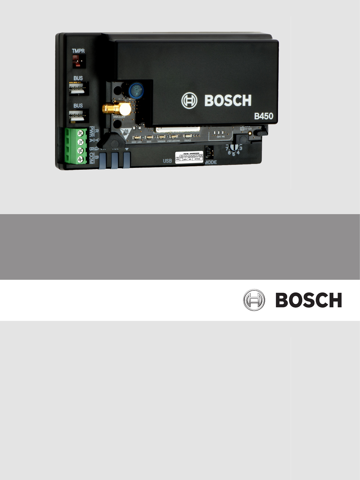
B450 module overview18629103754TXRXFigure 3.1: B450 Plug-in Communicator InterfaceCallout ᅳ Description1 ᅳ Tamper switch connector2 ᅳ Bus address swit
Bus address labelUse the bus address label to select the desired setting on the bus address switch, dependingon your control panel.PANEL ADDRESSESTXRX
More documents for Security access control systems Bosch B450


Related products and manuals for Security access control systems Bosch B450
 (4 pages)
 (12 pages)
© 2020, manymanuals.com. All rights reserved. | 0.530 s |
 Manymanuals.com
 Manymanuals.de
 Manymanuals.fr
 Manymanuals.it
 Manymanuals.pl
 Manymanuals.cz
 Manymanuals.es
 Manymanuals-pt.com
Comments to this Manuals