Bosch DVA-12T Installation Manual Page 24
- Page / 56
- Table of contents
- BOOKMARKS
- RAID Subsystem DVA-12T 1
- Table of Contents 3
- 1 Warnings and Certifications 5
- CB (Certified Worldwide) 6
- 2 Introduction 7
- 2.2 Enclosure Chassis 8
- 2.2.2 Front Panel Overview 9
- 2.2.3 Hard Drive Numbering 9
- 2.2.4 Rear Panel Overview 9
- 2.3 Subsystem Components 10
- 2.3.2 Drive Trays 11
- 2.3.5 DIMM Module 12
- 2.3.6 BBU 12
- 2.3.7 Power Supply Units 13
- 2.3.8 Cooling Modules 13
- 2.4 Subsystem Monitoring 14
- 2.5 Hot-swappable Components 15
- 3 Hardware Installation 16
- 3.5 Unpacking the Subsystem 18
- 3.6 Rack/Cabinet Installation 18
- 3.7 Drive Tray Installation 18
- 4 Subsystem Monitoring 21
- 4.2 Status-indicating LEDs 22
- 4.2.3 Controller Module LEDs 23
- 4.2.4 Ethernet Port LEDs 23
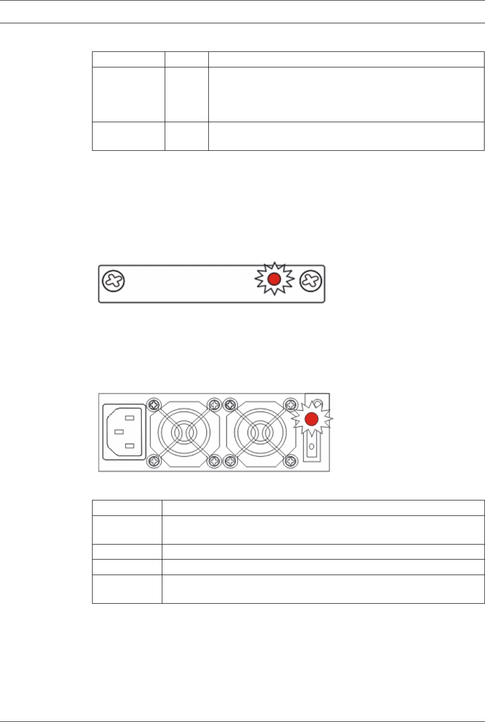
- 4.2.5 BBU Module LED 24
- 4.2.6 PSU LEDs 24
- 4.3 Audible Alarm 25
- C Monitoring 26
- 5.1 Cabling 27
- NOTICE! 28
- 5.3 Power On 30
- 5.4 Power Off Procedure 31
- 6.1 Overview 32
- • DIMM Module 33
- • Controller Module 33
- 6.3 DIMM Module Replacement 34
- 6.4.2 Procedure 36
- 6.5.1 PSU Module Overview 37
- 6.6.1 Cooling Module Overview 39
- 6.7.2 Replacing a Hard Drive 41
- 7 Specifications 43
- 7.2 Controller Specifications 44
- 7.3 Drive Tray Specifications 45
- 7.6 RAID Management 45
- 8 Spare Parts and Accessories 47
- 9Pin Outs 48
- 9.3 Main Power 49
- 10 Index 51
- Warning Alarms 44 53
Related products and manuals for Security access control systems Bosch DVA-12T
 (12 pages)
 (19 pages)
© 2020, manymanuals.com. All rights reserved. | 1.073 s |
 Manymanuals.com
 Manymanuals.de
 Manymanuals.fr
 Manymanuals.it
 Manymanuals.pl
 Manymanuals.cz
 Manymanuals.es
 Manymanuals-pt.com
Comments to this Manuals