Bosch INTEGRUS Specifications Page 12
- Page / 32
- Table of contents
- BOOKMARKS
- Integrus 1
- Data brochure 1
- 2 2
- 1. Introduction 3
- 2. System description 7
- LBB 4511/00 9
- LBB 4512/00 9
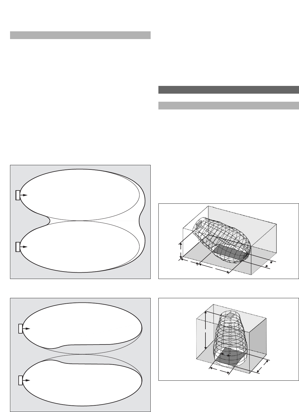
- ’ X is negative because 12
- area length width offset 14
- 3. System Specification 15
- 4. Transmitter 17
- 20 20
- 5. Radiators 21
- 6. Receivers, Battery 23
- Packs and Charging Units 23
- 7. Headphones 25
- 8. 6-Channel Interpreter 27
- Desk and Accessories 27
- Interpreter desks 29
Related products and manuals for Security access control systems Bosch INTEGRUS
 (136 pages)
 (19 pages)
© 2020, manymanuals.com. All rights reserved. | 1.027 s |
 Manymanuals.com
 Manymanuals.de
 Manymanuals.fr
 Manymanuals.it
 Manymanuals.pl
 Manymanuals.cz
 Manymanuals.es
 Manymanuals-pt.com
Comments to this Manuals